3-Phase Wiring Question (Start/Stop Switch)

All discussion about lathes including but not limited to: South Bend, Hardinge, Logan, Monarch, Clausing and other HSM lathes, including imports

Moderators: GlennW, Harold_V

Post Reply
NealinCA
Posts: 23
Joined: Mon Mar 24, 2003 12:37 pm
Location: Central Coast, CA, USA
Contact:

3-Phase Wiring Question (Start/Stop Switch)

Post by NealinCA »

I am finally getting around to wiring my old 16" Monarch Lathe.

Image

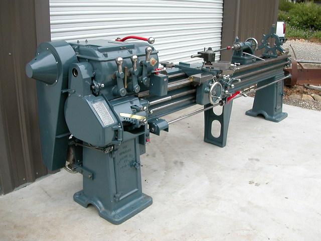
I just noticed that I had originally posted this picture exactly one year ago today...boy how time flies Image

It is 3-phase and this is my first time working with it. I dissassembled the lathe and wiring about 5 years ago, I have some diagrams and notes, but I think I am missing some part of the puzzle.

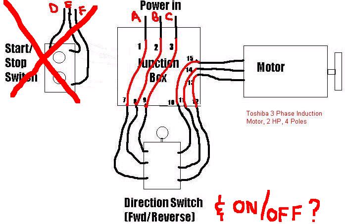
There is a junction box that all of the wires go in or out of and that is where I am confused. Image

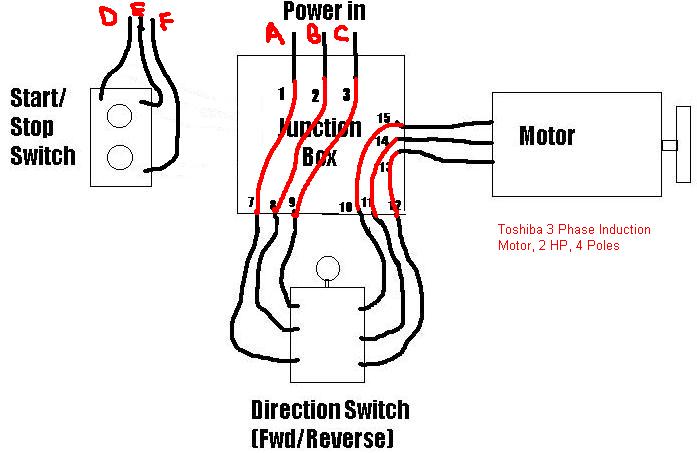
Here is a wiring diagram showing what I have to work with.

Image

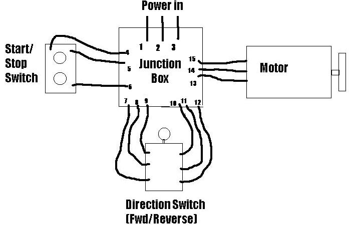
How do I hook up the wires labeled 1-9? I assume 10-12 hook to 13-15, I am just not sure how the start/stop switch (4-6) fit in.

Any input would be appreciated.

Thanks,

Neal Jennings
Atascadero, CA
Doug_C
Posts: 1254
Joined: Sat Jan 04, 2003 6:48 pm

Re: 3-Phase Wiring Question (Start/Stop Switch)

Post by Doug_C »

More data would be needed for the start stop switch and/or if there is a relay in the junction box or seperate overload units.

As a guess, without a relay, I would say 1-3 connect to 4-6 on the start switch, but 7-9 should come from the lower side of the start switch, only if it is 3 pole, single throw switch.

Otherwise 1-3 go to the top of a relay and 7-9 come from bottom relay connection points(after the overload heaters). Possibly 4-6 control the relay coil(one wire could be ground) to transfer power via relay using the start switch.

If there are any E-stop type functions, this may be a typical 3 wire control, where a relay gets dropped out from a latched in condition. More so on lathes with a foot brake option.


If that makes sense.


DC
Patenteux47

Re: 3-Phase Wiring Question (Start/Stop Switch)

Post by Patenteux47 »

Sorry, I can't help you with the wiring but I can tell you that your machine looks great. [img]/ubb/images/graemlins/grin.gif"%20alt="[/img] Thanks for posting the photo. I am green with envy. [img]/ubb/images/graemlins/tongue.gif"%20alt="[/img]
NealinCA
Posts: 23
Joined: Mon Mar 24, 2003 12:37 pm
Location: Central Coast, CA, USA
Contact:

Re: 3-Phase Wiring Question (Start/Stop Switch)

Post by NealinCA »

Thank you for the response. I took a closer look and found that I had my wiring diagram drawn wrong. It should look more like this...

Image

I basically have two flexible conduits coming off the back of the lathe, one from the junction box with wires A,B,C and one from the Start/Stop switch with wires D,E,F.

These had obviously been connected to something seperate from the lathe, posssibly a magnetic starter? Would that be needed for a 3ph induction motor?

The start/stop switch is a push button type. The start button is normally open and the stop is normally closed. Wires D and F are normally connected. When the start button is pushed, it would momentarily connect E with D and F. When the stop button is pushed D and F would be momentarily disconnected.

This dummy needs help.

Thanks again,

Neal
timekiller
Posts: 158
Joined: Sat Jan 04, 2003 12:33 pm
Location: Huntsville, AL U.S.A.

Re: 3-Phase Wiring Question (Start/Stop Switch)

Post by timekiller »

Notes & diagrams after getting cold, are harder to read and understand?

It gets worse, the older you get! [img]/ubb/images/graemlins/blush.gif"%20alt="[/img]

Ray [img]/ubb/images/graemlins/grin.gif"%20alt="[/img]
Doug_C
Posts: 1254
Joined: Sat Jan 04, 2003 6:48 pm

Re: 3-Phase Wiring Question (Start/Stop Switch)

Post by Doug_C »

I have attached a basic 3 wire circuit for controlling a relay. The relay can be any basic contactor sufficient for the 1-3 phase application desired. The control voltage can be pulled off the main feed, or off of a low voltage control circuit. The coil on the contactor can be the limiting factor there.

M1 is the contactor coil. Once the start button is pressed, the coil latches due to the auxiliary contact taking over once the start button is released. If either the stop button or the overload opens the circuit. The contactor will drop out.

The L1-3 wires will go to the top 3 terminals of your contactor and 7-9 would connect to the bottom 3 terminals. Many motor controls have heater type overloads built into the contactor body. While others tag on in some fashion. Overloads are current rating specific and selection is required based on the full load amps multiplied by 1.15-1.25. These are a sustained over current devices. If they heat up, thier purpose is to disconnect power and require a reset. This is an indication of over capacity on the motor or a poorly fed supply.

The setup you have now uses a center off tumbler style switch, but I see no overload system in your drawings. I would not rely solely on a circuit breaker for motor protection.

Image

I must say, what a nice looking nostalgic lathe you have there.

DC
J Tiers

Re: 3-Phase Wiring Question (Start/Stop Switch)

Post by J Tiers »

In my opinion, the setup Doug shows should be installed on every machine.

A few reasons:

1) if power drops for some reason, the relay also drops out and the machine will not re-start unexpectedly when power returns.

2) it is easy to wire in E-stops in convenient places without needing heavy current switches

3) you can put a lockout switch in easily for when you change tools etc. Just put a toggle switch in the relay line, located within reach but out of the way, and guarded so the toggle isn't hittable if something falls etc.
Now you cannot turn the machine on unless the toggle is set to "on", and so it is that much safer to change tools.


I like to wire the lockout switch on the L1 side of the circuit, and then put a clearly visible pilot light in parallel with M1 and the other switches and circuitry. That way, if the pilot is on, the machine can be seen to be in the "armed" condition.
NealinCA
Posts: 23
Joined: Mon Mar 24, 2003 12:37 pm
Location: Central Coast, CA, USA
Contact:

Re: 3-Phase Wiring Question (Start/Stop Switch)

Post by NealinCA »

Thank you for the additional information.

You said...
The setup you have now uses a center off tumbler style switch, but I see no overload system in your drawings. I would not rely solely on a circuit breaker for motor protection.

I would like to put power to the lathe this weekend as I have a project that I can't do in my smaller lathe. I would like to wire it up without spending much money.

Although not ideal, will this setup work?

Image

If it will get me going for now that would be great. I will take your advice and go back and add some overload protection.

Thanks again,

Neal
Doug_C
Posts: 1254
Joined: Sat Jan 04, 2003 6:48 pm

Re: 3-Phase Wiring Question (Start/Stop Switch)

Post by Doug_C »

Hi Neal,

It will put power to the motor. The tumbler switch should be Forward/OFF/Reverse. If it is not a center off switch, then you will most definitely need a control circuit as described.

Whether your current setup will work depends on the correct connections and/or motor condition. If it comes alive and only goes forward or reverse when you switch on the breaker, you'll know what needs to be done.

With no overloads and a potential problem...... while you are standing around scratching your heads wondering why it won't run. The magic smoke could rise up from the ashes of almost anything in the circuit. Not perfect insurance, but better than nothing. After all, I think they are more of an indicator that something is not happy during operation, than a quick acting breaker on startup.

I can only express concern of not putting the overload in ASAP. I know how things can get overlooked if just getting it running until we get around to it. Getting around to it is easier to put off till it is forgotten?

Be safe,

DC
NealinCA
Posts: 23
Joined: Mon Mar 24, 2003 12:37 pm
Location: Central Coast, CA, USA
Contact:

Re: 3-Phase Wiring Question (Start/Stop Switch)

Post by NealinCA »

Hi Neal,


I can only express concern of not putting the overload in ASAP. I know how things can get overlooked if just getting it running until we get around to it. Getting around to it is easier to put off till it is forgotten?

Be safe,

DC

OK you are convincing me to do it right the first time.

I am at the bottom end of the electrical food chain Image, so I will need some help on parts selection. I need to know what to ask for when I go to the parts house.

I was looking in my Grainger catalog. Is this what I need?

Electrical > Starters and Contactors > Definite Purpose Contactors

Image

Contactor,20 A,3 Pole
Definite Purpose Contactor, Inductive Full Load Current 20 Amps, Resistive Full Load Current 25 Amps, Number of Poles 3, Power Rating @ 120 VAC 1 HP, Power Rating @ 230 VAC Single Phase 2 HP, Power Rating @ 230 VAC Three Phase 5 HP, Coil Voltage @ 60 Hz 208-240 VAC, @ 50 Hz 220 VAC

Grainger Item: 2CF90
Price (ea) : $29.60
Manufacturer: SQUARE D
Mfg. Model#: 8910DPA13V09
Ship Qty : 1
Sell Qty (Will-Call) : 1
Usually Ships : Today
Catalog 395 Page: 378

Let me know if I am on the right track, then we can go from there.

Thanks,

Neal
Doug_C
Posts: 1254
Joined: Sat Jan 04, 2003 6:48 pm

Re: 3-Phase Wiring Question (Start/Stop Switch)

Post by Doug_C »

That is only the contactor portion of the starter circuit.

Select a contactor rating a little over the full load rating of the motor.

On pages 370 or 375 of cat 395 or Here is a link to the PDF page. Their optional catagories list the N. O. Aux contact as 4B972.

I do not like the melting alloy overloads. As these are one shot use and not resetable. The starters on page 375 use heater overloads on 376. Read the description at the top of the page for required ratings selection based on your specific motor.

You will need to purchase the aux contact and 3 overloads, to install on this assembly.

[img]/ubb/images/graemlins/smirk.gif"%20alt="[/img]No cheap prospect , eh? Unless you have other sources for used contactors that fit the bill.

I did not have time to look for any manual type overload blocks by themselves. I have seen them a long time ago in use, but not in a catalog so far.

DC
Post Reply